Cisco UCS – Creating Service Profile Templates – Part 1
- Blog
- Networking
- Post
Introduction
Service Profile Templates can make it easy for you to provision many servers because it will allow you to quickly create multiple service profiles having the same basic parameters like say the number of vNICs and vHBAs. In this video, from TrainSignal’s Implementing Cisco Unified Computing System (UCS) Training Cisco UCS expert Jason Nash will show you the required steps to creating a Service Profile Template in your Cisco Unified Computing System.
(Instructional video below provides a walkthrough of the steps contained in this article.)
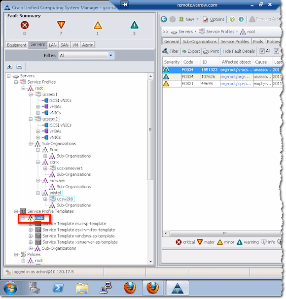
To create a service profile template from within your Cisco Unified Computing System Manager, navigate to Servers > Service Profile Templates, and right-click on root.
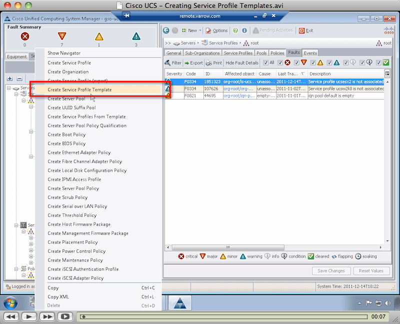
On the context menu, select Create Service Profile Template.
Identify Service Profile Template
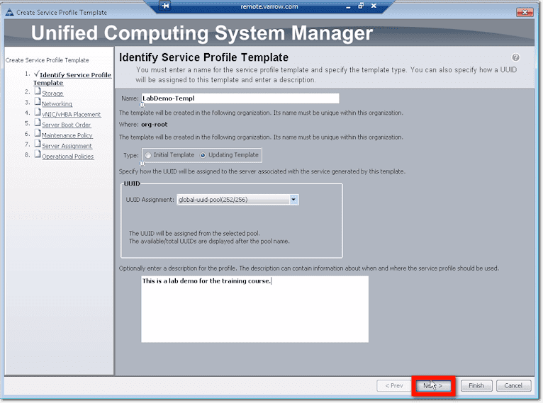
The first thing you’ll be asked to enter is your service profile template’s name. For best practice, use a naming scheme that will help you quickly differentiate this from something else like a profile or a policy. For example, here, we used a dash followed by “Templ” for template.
Next, choose a template type. The options are Initial Template and Updating Template.
Initial templates don’t have linkages to the servers created based on them. So if you make changes to items defined by initial templates, those changes won’t be propagated to the servers.
Updating templates, on the other hand, do have links to servers created based on them. So changes to an updating template will be cascaded to those servers. In our example, we selected this particular kind of service profile template.
After selecting a template type, choose an appropriate UUID assignment. This will tell the system where to pull the unique identifier from when deploying a service profile. If you select Hardware Default, the system’s going to use whatever’s on the blade. But then that won’t be migrated if the service profile is moved to a new server. In our case, we opted to obtain the UUID from a pool that we created earlier.
Lastly, for this screen, you might want to enter a profile description indicating when and where this particular service profile template should be used.
Once you’re done with all that, click the Next button.
Storage configuration
The first group of configurations you need to set up are the configurations for storage. Now, when you start your storage configurations, the first thing you’ll be asked to do is to select a local disk configuration policy. But if you’re doing boot from SAN, you may not have a local disk in the first place.
For those who aren’t comfortable yet with boot from SAN, let me tell you that this technology has greatly improved over the years and it’s much better now. In fact, almost all of our implementations have zero local disks installed on the blades. Besides, Cisco UCS is built on the foundation of boot from SAN. If you want to do mobile service profiles, you just have to go this way.
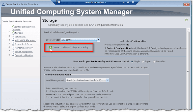
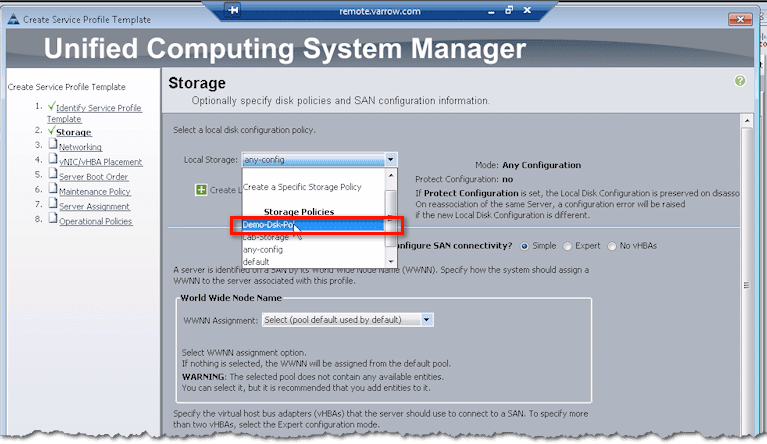
So going back to our discussion, if you intend to boot from SAN, one of the options you can choose for the local disk configuration policy is any-config. As the name implies, it means any configuration. Whatever the disk is set for, just leave it. And often, that’s what we’ll do for “boot from SAN” if there are still disks in the blades. That way, we don’t touch them and mess with them.
In case the drop-down list doesn’t have the kind of policy you want to implement, then you might as well create your own. In this case, just go ahead and click Create Local Disk Configuration Policy.
Note that the policy you’re about to create will be saved and can be used not just in this template but also in other templates in the future.
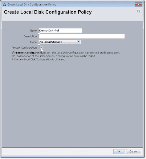
Ok. First, give this policy a name. Again, we recommend you use a naming scheme. For instance, because this is a policy, you might want to end the name with “Pol”. If you want, you could also add a description.
From the drop-down list box labeled Mode, select the appropriate mode for your Local Disk Configuration Policy. Because, in our case, we wanted to boot from SAN and we didn’t have any disks on our blades, we selected No Local Storage. Whether we checked or unchecked the Protect Configuration check box wouldn’t have mattered because we didn’t have any local disk. Click OK.
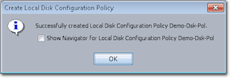
Barring any unforeseen events, you should see a message box saying “Successfully created…”. Click OK to proceed.
You may now select the policy you just created from the drop-down list of Local Storage (or local disk) configuration policies.
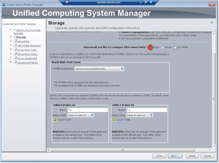
Next up are the SAN connectivity configurations. This is where you’ll create your virtual HBAs or vHBAs.
Of course, if you select No vHBAs from the three options following the question “How would you like to configure SAN connectivity?”, then no vHBAs will be created. This is what you choose if you’re not going to use Fibre Channel. You’ll then have to boot from local disk, iSCSI, or from network via PXE.
On the other hand, if you choose Simple, vHBAs will be created. But first, you need to specify where you’re going to assign your World Wide Node Names (WWNN) from. Here, we already got a pool created, so we selected that pool from the WWNN Assignment drop-down list box.
The system will then allow you to create vHBAs on Fabric A and Fabric B. You will need to specify which VSANs they should belong to. Select those from the two drop-down list boxes labeled Select VSAN. If you haven’t created VSANs yet, you can go ahead and create them by clicking the Create VSAN links.
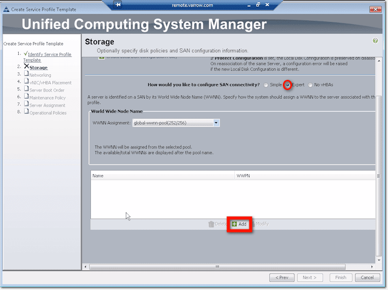
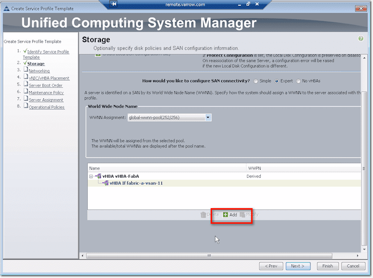
Another way to configure SAN connectivity is through the Expert method. Like in the Simple method, the first thing you’ll need to do is specify the WWNN Assignment. After that, you can proceed to create virtual HBAs. Just click the Add button.
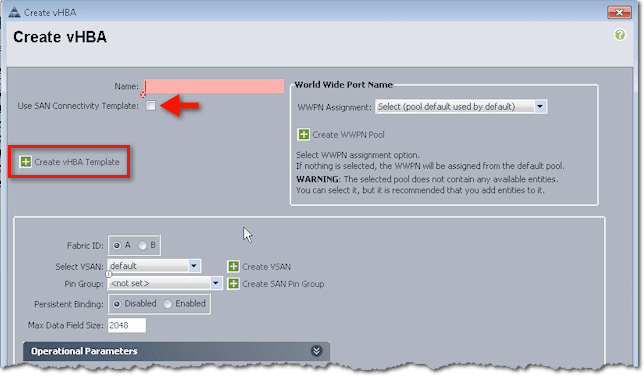
You’ll then be presented with a couple of options. Near the top of the screen, you’ll see that it’s possible to use a SAN Connectivity Template, which may already spell out a lot of the settings you see in the lower half of the screen. To create such a template, just click the link that says Create vHBA Template.
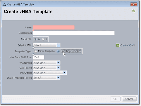
There you’ll see a bunch of settings like the Fabric ID, Template Type, WWN Pool, QoS Policy, and so on.
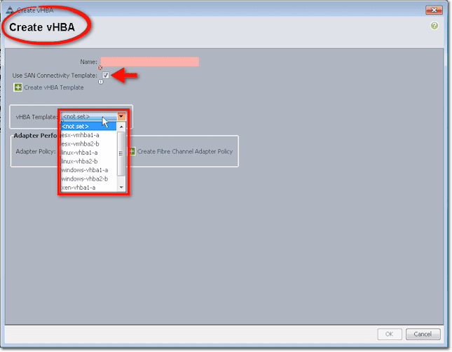
After filling up all those fields and clicking OK, you can use that template for creating a vHBA. To do that, click the Use SAN Connectivity Template check box (this is inside the Create vHBA dialog box and not in the Create vHBA Template dialog box) and select the name of the vHBA Template you created earlier from the vHBA Template drop-down list box.
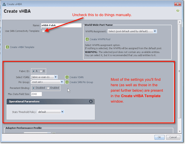
Now, in case you don’t want to use a template and, instead, would like to do things manually, leave the Use San Connectivity Template check box unchecked. You can then proceed to configure the settings in that dialog box. You start by assigning a name, choosing a Fabric ID (A or B), and then proceed down the settings in the lower sections of that dialog box.
Typically, you should do one set of configurations for Fabric A and another one for Fabric B. So you set the VSAN, Pin Group, Persistent Binding, and so on.
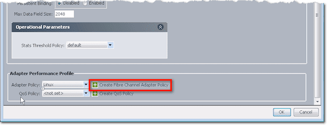
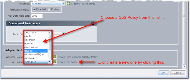
If you scroll down to the panel labeled Adapter Performance Profile, you’ll find a couple of settings: Adapter Policy and QoS Policy. If you expand those lists, you’ll see some preset adapter policies.
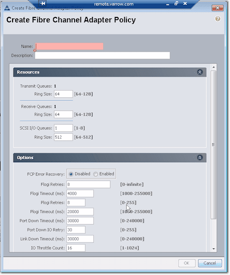
Cisco already set these for the major OSes, so if you want to use an adapter policy for say Linux, then I suggest you just choose the default, unless you really have a reason to change some of the settings. To see what settings are specified in an adapter policy, click Create Fibre Channel Adapter Policy.
These are the settings you’ll find in there:
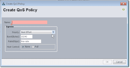
Similarly, you can select a QoS Policy from the list or specify your own settings by creating a new QoS Policy.
These are the settings you can specify in a QoS policy:
So, assuming you finished configuring all settings for Fabric A and clicked the OK button at the bottom, you’ll see something like this in the succeeding screen:
Remember that you may have to configure Fabric B as well. To configure Fabric B, just click the Add button as shown at the bottom of that screenshot. You’ll then be brought back to the Create vHBA dialog box. So again, you assign a name, select B for the Fabric ID, and configure the rest of the settings as before.
Notice that those were practically the same settings found in the Create vHBA Template dialog box. Imagine going through the same process each time you create a vHBA. So as you can see, creating a template can speed things up if you need to create similar vHBAs in the future.
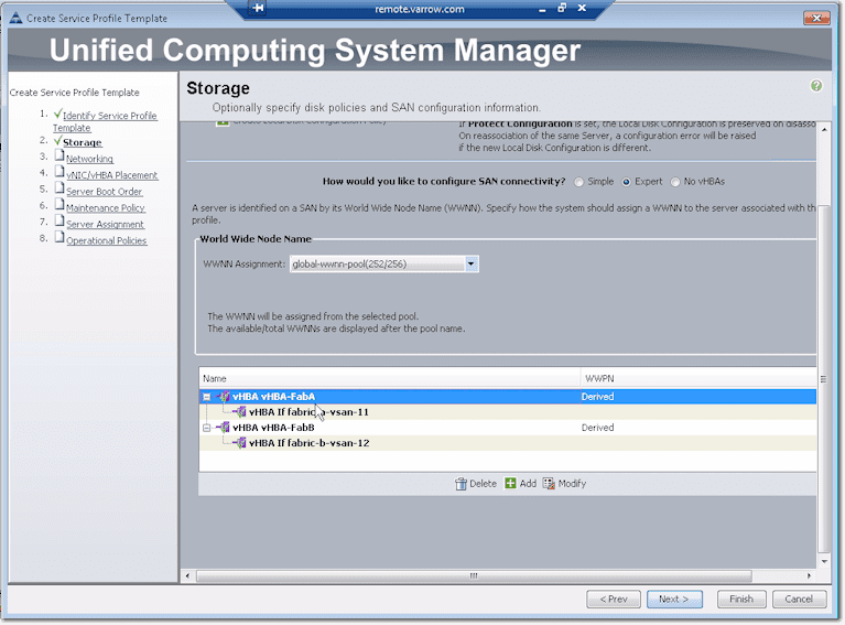
Once you have finished setting configurations for Fabric B and have clicked the OK button, you’ll then see something like this in the succeeding screen.
If you need to make some changes, just click the Modify button. If not, click Next. That will bring you to networking configuration.
Networking configuration
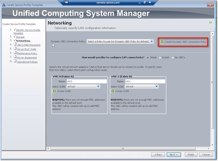
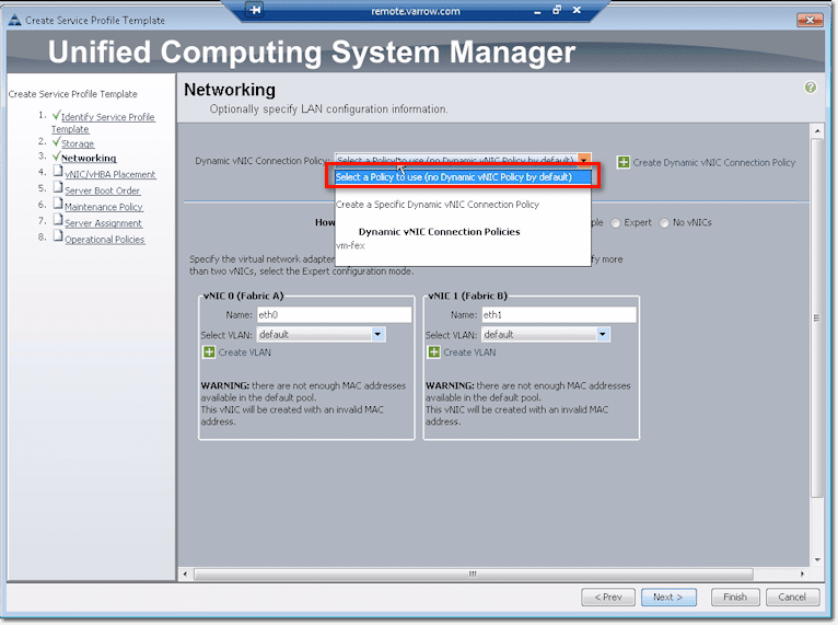
Up at the top of the screen, you’ll see what is known as a Dynamic vNIC Connection Policy. This has something to do with virtualization, hypervisor integration, which will allow you to take a VIC (Virtual Interface Card) like an M81KR or a VIC 1280, slice and dice some vNICs (virtual network interface cards), and push those vNICs up to virtual machines.
So when a virtual machine sees a NIC and sends data, it goes directly to the fabric interconnect to be switched in hardware, bypassing like VMWare software’s vSwitch.
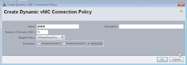
But to do that, you need to create a Dynamic vNIC Connection Policy.
For such a cool feature, this policy is actually very simple. It only requires a name, the number of dynamic vNICs that will be affected by this policy (this is on a ‘per fabric’ basis), an adapter policy, and a protection (which you normally set to ‘Protected’, which will allow it to do fabric failover should a connection up to the fabric fail).
But that’s just for VM-FEX or VMWare integration. If you’re not doing that, you don’t have to create a Dynamic vNIC Connection Policy. Just select “Select a Policy to use (no Dynamic vNIC Policy by default)” from the drop-down list.
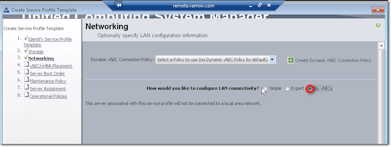
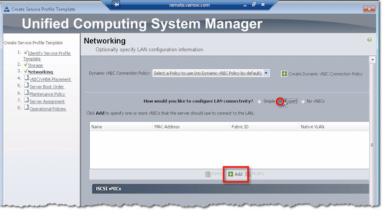
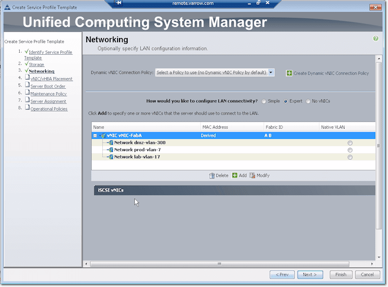
Down that screen, you’ll see some options similar to the vHBA config.
Well, if for some reason you want to install a service profile without network connectivity, just select No vNICs.
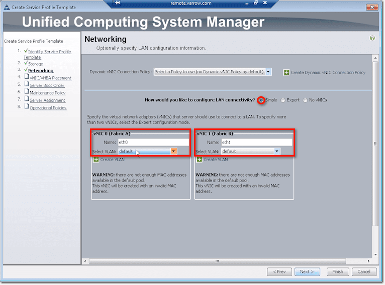
The default, however, is the option labeled Simple, which will create two NICs. You should give each NIC a name and assign which VLAN it should belong to.
The Expert option here is similar to the Expert option of the vHBA configuration. Click Add to do things manually.
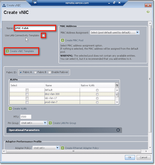
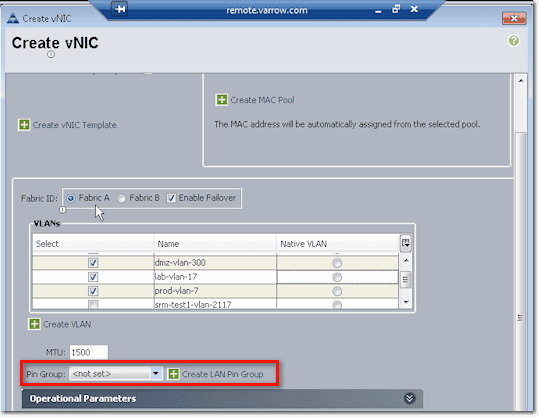
Again, just like when you were working with vHBAs, you start by giving the vNIC a name. Then, if you have a LAN Connectivity Template ready, you can check the Use LAN Connectivity Template checkbox and then select the template you want from the list box. If none of the existing templates have the settings you need, you can create your own by clicking Create vNIC Template.
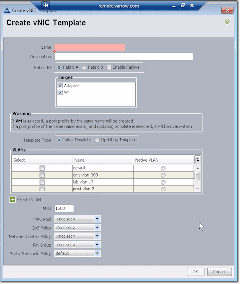
This will bring up the Create vNIC Template dialog box.
The configurations you set here can be used later on in the future when you need to create additional vNICs.
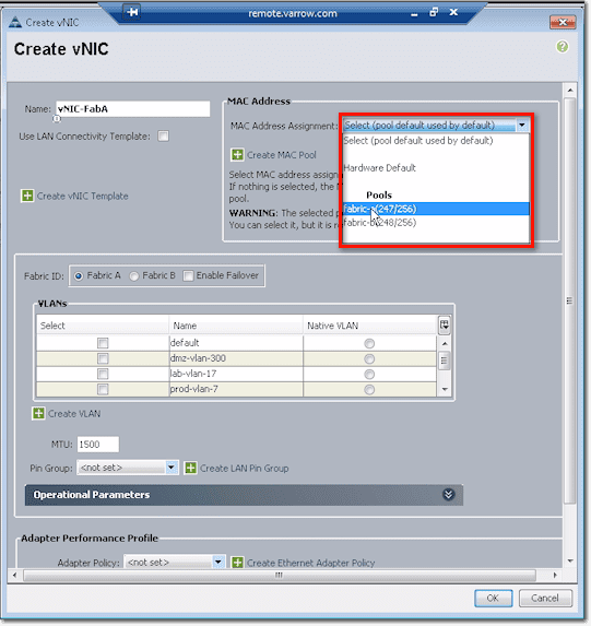
For the MAC Address, you can pull those from a pool. The reason why we have Fabric A and Fabric B pools is so that you can look up a MAC address and tell which fabric in UCS it came from.
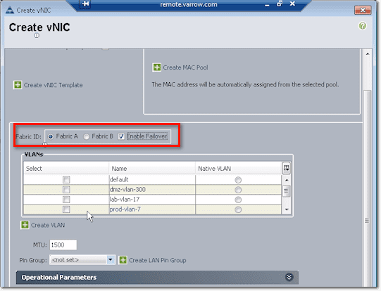
After that, you need to indicate whether this vNIC will belong to either Fabric A or Fabric B. You might want to check the Enable Failover checkbox so that if the link up from the FEX and the chassis up to the interconnect (or all the uplink from the interconnect to the core switch) fail, it will send down a disconnect message to the chassis and it will fail the vNIC on A to B. As a result, the host will still see as if everything is good.
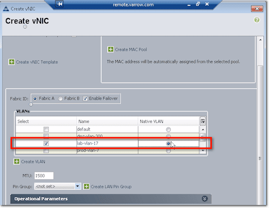
Next up is the VLAN config. You need to associate the vNIC to at least one VLAN. Just tick the checkbox beside the VLAN you want to associate it to. In the screenshot below, we ticked both the checkbox of lab-vlan-17 and the option button to the right of it, under the column named Native VLAN. That means, frames coming in and out are not tagged.
So if this was Windows installed directly on hardware, that NIC would act as if it were on a rack server plugged into a port on a switch on lab-vlan-17.
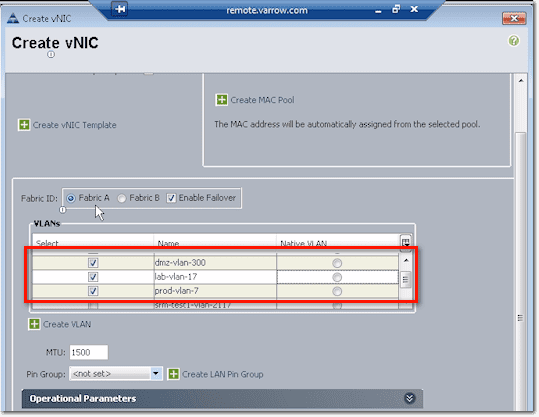
But then if this is VMWare, you can trunk a bunch of ports by selecting a bunch of those VLANs. Then you can either enable Native on one VLAN or tag everything. Basically, when you tick the checkboxes of certain VLANs, that’s going to trunk those selected VLANs up to this particular VNIC.
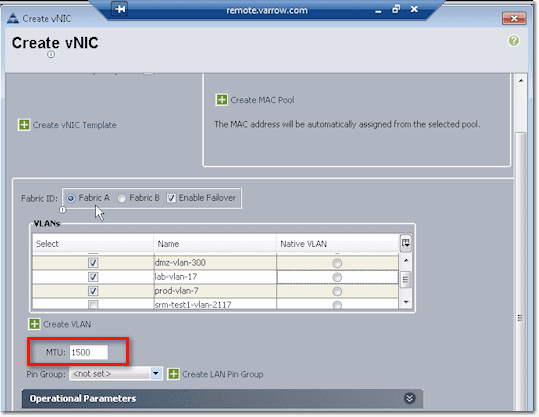
The next to set is the MTU size, wherein MTU stands for Maximum Transmit Unit. 1500 is the default for ethernet. But if you’re doing jumbo frames for ISCSI, NFS, or something like that, you’ll have to set this to 9000 or whatever your matching configuration is up level on your switches.
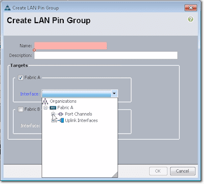
Pin Group settings is where you specify where you want to pin Ethernet traffic from a vNIC on a server to an uplink Ethernet port or port channel on the fabric interconnect.
So for example, you can pin (this is after clicking the Create LAN Pin Group link shown in the screenshot above), to a port channel or individual link on Fabric A.
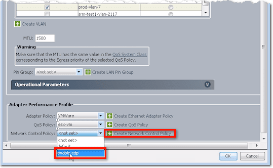
The last batch of settings you need to configure when creating a vNIC are the Adapter Peformance Profile settings. This includes the Adapter Policy, QoS Policy, and Network Control Policy.
We already talked about the Adapter Policy and QoS Policy earlier, so let me show you the Network Control Policy this time.
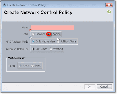
Here we have a Network Control Policy for CDP named enable-cdp. To create that policy, just click Create Network Control Policy (refer to screenshot above), and this is what you’ll see:
CDP stands for Cisco Discovery Protocol. If you’ve ever been on a Cisco switch and have run the “show CDP neighbors” command to show what other switches or devices are connected, then you’ve used CDP.
It’s a Layer 2 protocol that’s normally used to gather basic information from devices that support CDP without requiring much else other than a connection and a very small amount of bandwidth. So basically, it’s useful for inventory or troubleshooting purposes.
To continue with our discussion, you would normally create a Network Control Policy named enable-cdp and then enable CDP in the Create Network Control Policy screen. In most cases, that’s going to be pretty much what you need to do. That policy is going to apply CDP up to those links you selected earlier.
So if this was VMWare, which incidentally can listen and send CDP information, information can then be processed.
After clicking the OK button at the bottom of the Create vNIC window, you’ll be presented with something like this:
In the first column, you’ll see your VLANs. In the third column, the information you see there means that the LAN starts in fabric A and fails to B. After ensuring everything’s all set, I would normally create a second vNIC that would then fail from B to A.
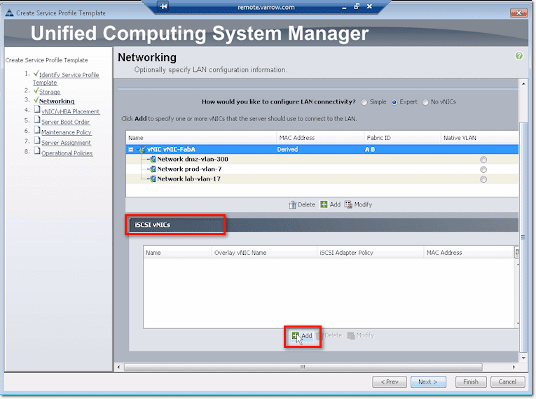
For those of you who are doing boot on iSCSI, there are some special vNIC configurations that you need to set. Go down to the lower portion of that screen, expand the section that says iSCSI vNICs, and click Add.
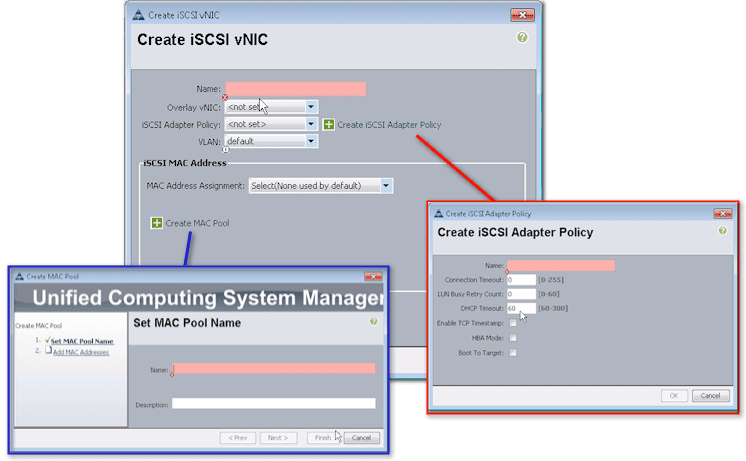
Once you’re inside the Create iSCSI vNIC dialog box, do the following:
- Assign a name,
- Set an Overlay vNIC (you’re basically creating something overlaying a standard vNIC),
- Set an iSCSI Adapter Policy or create one (the dialog box for which is shown in the screenshot below),
- Select the virtual LAN (vLAN) associated with this iSCSI vNIC,
- Set the Mac Address associated with this iSCSI vNIC, and
- If necessary, create a MAC Pool that you want to associate with this iSCSI vNIC (dialog box for this is also shown below)
Conclusion
It’s fairly simple. Just remember that you need this configuration, which is different from the vNIC configuration, if you boot from iSCSI. Are you still there? If so, we’ll move on to Part 2 of this post and discuss placement policies.
In the meantime, check out Jason Nash’s brand new training Implementing Cisco Unified Computing System (UCS) Training.


